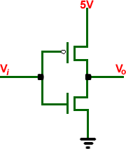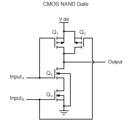


The p-channel device is identified by a "bubble" on the gate input. Notice too that the gates for the p- and n-channelĭevices differ. In this caseīulk-substrate connection is not indicated. 1 (c) show the schematic symbols for p- and n-channel MOSFET transistors. Symbols are most commonly used in documenting analog CMOS circuits.įig. Transistors when the source-bulk connection has been shorted 1 (b) show the symbols for the p- and n-channel MOSFET N-channel bulk connections are typically tied to the V SS rail. P-channel bulk connections are typically tied to the V DD rail and Must be properly connected before power is applied.Ĭonnections for MOSFET transistors are normally connected to a power supply rail. The bulk,Īlso called the bulk-substrate or substrate, is shown unconnected in this schematic symbol but Show the drain(D), gate(G), source(S), and bulk(B) connections for the transistor. The MOSFET schematic symbols shown in Fig. Schematic Symbols for the MOSFET Transistor Schematically MOSFET transistors are typically identified

This is adequate for an introduction to simpleĬMOS circuits where switching speeds, propagation delays, drive capability, and rise and fall Transistors can be treated as simple switches. V DDor V SSpower supply rails for a given input logic state. The complementary p-channel and n-channel transistor networks are used to connect the output (MOSFET) connected in complementary configurations. Operation of these CMOS devices through a few exercises in constructing simple CMOSĬombinational logic circuits such as AND, NAND gates, OR, NOR gates andĪre created using both p and n-channel Metal-Oxide Semiconductor Field Effect Transistors Students in introductory electronic circuits classes can gain insight into the Inherent lower power requirements, high operating clock speed, and ease of implementation at The CMOS structure is popular because of its Signal processing and communication circuits. Transistor count circuits found in everything from complex microprocessor integrated circuits to Logic devices are the most common devices used today in the high density, large number The paper concludes with a discussion on using theĬD4007 CMOS transistor array package for implementing CMOS logic circuits.Ĭomplementary Metal-Oxide Semiconductors (CMOS) Provided which show how the logic circuits can be simulated at the SPICE level incorporating Included in this paperĪre examples of several CMOS logic circuits implemented at the transistor level along with aĭesign method for the implementation of CMOS combinational logic circuits. Transistors are approximated as ideal switches. Material presented is suitable for use in an introductory circuits course. Technique for creating CMOS combinational circuits using discrete William of Electrical and Computer Engineering Transistor Level Implementation of CMOS Combinational Logic Transistor Level Implementation of CMOS Combinational Logic Circuits


 0 kommentar(er)
